Modernizing the heating system in a private house may require installing two boilers at once, connecting them in shared network. What sequence should be followed? How to connect two boilers into one system, what must be taken into account if there is a need to share a gas boiler with a solid fuel, electric or heating equipment, running on liquid fuel.
How to connect two boilers together?
I would like to clarify right away that it’s easy to connect two boilers to different types fuel into one system is one of possible solutions lack of power problems installed equipment. It is also possible to connect more than two models into one network.For what purposes may it be necessary to connect two boilers into one system? There are several good reasons why this is advisable.
- Lack of power. Incorrect calculation of equipment or additionally added living space can lead to the fact that the boiler power may simply not be enough to maintain normal temperature coolant.
- Increase functionality. It may be necessary to connect two boilers to one system to, for example, increase the time battery life equipment. For example, if the main source of heat is a solid fuel boiler, then for its operation it is necessary to constantly add firewood, which is not always convenient, much less practical.
By installing an electric boiler or gas heating device after it, you can solve this situation as follows. As soon as the firewood or coal has burned out and the coolant has begun to cool, additional heating equipment is switched on in the process and continues to heat the room until the owner adds a new batch of firewood in the morning.

As you can see, connect two heating boilers on different types of fuel, this is practical, in addition, it may be due to an urgent need associated with a lack of equipment performance.
How to connect two gas boilers in parallel
There are two schemes for connecting gas and any other water heating equipment. You can connect two boilers to one heating system:- Sequentially - in this case, one unit will be installed after another. In this case, the load will be distributed unevenly, since the main boiler will constantly operate at full capacity, which can lead to its rapid failure.
- Parallel. In this case, the heated area will be divided into two parts. Heating will be carried out by two installed boilers. Parallel connection of two gas boilers is usually used in cottage houses and buildings with a large heated area.


For parallel connection, it is necessary to install a controller and also develop a cascade control circuit. Answer the question of how to connect the two gas boilers Only a competent specialist can do this in each specific case.
How to connect two boilers - gas and solid fuel?
 Combining gas and solid fuel boilers into one system is a simpler task, for which it is necessary to take into account the main features that distinguish the operation of these two types of equipment.
 Models of gas and solid fuel equipment can be installed in one network sequentially. In this case, TT boilers will play the role of the main source of heat supply.
The principle of their operation will be that gas equipment will turn on for heating only if the operation of the main unit for some reason becomes impossible. Also, usually a gas boiler is assigned the task of heating water, of course, if such a function is provided. During the design of such a system, these features must be taken into account.
You will also definitely need to agree on the chosen scheme in the gas sector and get everything there necessary permissions, including technical specifications and connection project.
How to combine gas and liquid fuel boilers
 For safety reasons, such a connection requires that conditions be created under which it is possible safe work two types of equipment at once. To do this you need to do the following:
 - Install a general system for monitoring the operation of water heating equipment. The combined use of liquid fuel and gas boilers implies the installation of common automation. It, in turn, is connected to control sensors, which send a signal to turn on if the main heat source stops working.
- Install control valves. Shut-off valves operating in automatic mode can also be used.
Advantages of installing several boilers on one network
Connect two boilers at the same time: floor-standing and wall mounted boilers may be necessary if the area of the room as a result construction work, increased sharply. Even if the equipment was initially purchased with a power reserve, it may not be enough to heat additional rooms larger area. In this case, an additional boiler is installed, connected to common system heating. The advantage of this solution is:- Possibility of simultaneous control over the operation of all equipment.
- Savings due to the choice of the main type of fuel.
- Possibility of longer equipment operation.
Practice shows that it is possible to simultaneously install two or more boilers in one network. With every additional element overall performance and efficiency drops significantly. Therefore, the feasibility of simultaneous installation of four or more units of water heating equipment is completely absent.
The installation of a heating system in a private house begins with the installation of a boiler. Many suburban communities do not have a natural gas pipeline. Instructions on how to properly connect a solid fuel boiler will alleviate this problem.
Necessary conditions for the correct connection of a solid fuel boiler to the heating system
- A separate room for the boiler room is selected. The area is about 7m2. Boiler room in a separate building perfect option. Loading fuel into the boiler room can be made easier. Sufficient in the area of the receiving hopper with outside where, for example, coal will be unloaded, install a so-called chute. Having unloaded the fuel into the receiving hopper, the coal is poured down the slope into the boiler room on its own.
- It is preferable to place the heating boiler below the 0 floor level. This option boiler installation ensures ideal circulation of coolant in the heating system without the use of a circulation pump.
- The base for the boiler must be made of a concrete pad with an even top layer. Thickness concrete screed 10 cm. The base area under the boiler should be 20 cm larger than the dimensions of the connected boiler. On the firebox side 40-50 cm.
- According to SNiP standards and fire safety requirements, the distance between the boiler and the wall is 50 cm. From the side combustion hole, fireboxes, the distance to the opposite wall is at least 1.3 m.
- The installed heating boiler should not have gaps between the base and the body.
- It is necessary to connect the boiler to the heating system steel pipe at least 1 meter long at the inlet and outlet of the pipeline. Connect the boiler to the heating system with copper and polymer pipes wrong.
Below is the diagram applied correct connection solid fuel boiler.
There are many connection methods. Let's consider one of the simple and reliable connection methods.
A safety group is installed from the boiler on the direct pipeline. After the safety group, a tee for the bypass is installed. Next, the supply is connected to the heating system wiring. Having given up its heat in the heating system, the coolant returns to the boiler through the return pipe. To avoid the main disease in the operation of solid fuel boilers, condensation, which negatively affects the integrity of the boiler, a thermostatic three-way valve is installed, connected to the return line on the bypass, set to a temperature of 50-60°C. When heated, the coolant circulates through a small circuit through a three-way valve. A temperature of 55°C prevents the formation of condensation on the inner walls of the boiler. A circulation pump is installed after the three-way thermostatic valve. As soon as the return temperature reaches 55°C, the three-way valve opens and the heated coolant flows into the heating circuit to the radiators.
Connecting a solid fuel boiler paired with a gas boiler, diagrams and features
The connection diagram for a solid fuel boiler in parallel with a gas boiler differs from the installation of two solid fuel boilers. The requirements for the boiler room, where the main condition is air exchange, also differ:
- The area of a boiler room with a gas boiler, as recommended by fire authorities and the gas service, is calculated as follows: 1 kW of power - 0.2 m 3 with a ceiling height of 2.5 m, but not less than 15 m 3.
- A boiler room with a gas boiler must be equipped with a window with a window, the size of which is 0.03 m2 per 1 m3 of room volume.
- The entrance door of the boiler room must open only to the street. The door width is at least 80cm.
Gas boilers are available in two versions. Floor and wall. The requirements for installing a floor-standing gas boiler are the same as for a solid fuel boiler. The length of the pipe connecting the chimney and the boiler is no more than 25 cm. If the boiler is coaxial, the pipe for removing combustion products is installed at an angle of -3°. Otherwise, a separate ceramic or lined pipe is required for a gas boiler stainless steel with a hatch to remove combustion products, and a tee with a tap to remove condensate is installed at the bottom of the pipe.
A gas and solid fuel boiler are connected in parallel to the heating system in several ways. The schemes are different, it is not necessary to know them all, it is enough to understand the features that must be taken into account when using this combination of boilers in relation to your premises:
- Use the heat exchanger effectively. It will separate the open and closed heating circuits. Connect the boiler to one of the circuits, and connect the second boiler to the second circuit. A solid fuel boiler, capable of raising the coolant temperature to 115°C, heats the secondary closed circuit to which the gas boiler is connected. The gas boiler is adjusted to a temperature of about 50-60°C. The main load will be taken on by the solid fuel boiler. As the fuel burns out, the gas boiler will automatically turn on, heating the secondary circuit of the heat exchanger. The secondary circuit is equipped with a diaphragm expander. A closed expansion tank protects radiators from excess pressure. With this scheme of a connected solid fuel boiler, it is possible to install an open expansion tank directly in the boiler room under the ceiling.
- The use of a hydraulic arrow for parallel connection of boilers is used mainly in houses with large area. The operating principle of this system is as follows. The heating solid fuel boiler is installed first with circulation pump, for example, 25/60 installed on the return pipe. Mounted on the pipe between the boiler and the pump solenoid valve MD, which regulates the operation of the boiler circulation. Mandatory installation of a configured safety valve on the supply pipe. Shut-off valves are not installed on the supply side. The gas boiler is installed second. Through a tee, the boiler is connected through the supply pipe to the pipe from the solid fuel boiler and then connected to the hydraulic needle. Shut-off valves are not installed on the switch. On the second boiler, a pre-set safety valve is installed on the supply. A closed expansion tank is installed from the hydraulic needle on the return pipeline to the tee. Then, through a tee on the pipe, it is connected first to a gas boiler with the installation of a circulation pump of lower power than that of the first boiler. A valve without a servo drive is installed after the pump. Next, a solid fuel boiler is connected from the tee on the return pipeline. The use of a manifold after the hydraulic boom makes it possible to collect several heating circuits with pumping groups on each of them. Collectors make it possible to configure each circuit individually according to the loads on heating devices.
- Another method of parallel connection of boilers, when a solid fuel heating unit is installed first, a gas heating unit is installed second, and between them a check petal valve is installed on the supply pipeline, operating in the direction from the first heating unit. Before check valve a bypass is installed connected to a three-way thermostatic valve set to a temperature of 55°C. A circulation pump is installed on the return pipe between the thermostatic valve and the boiler more power than in gas. The gas boiler is connected through a tee on the supply pipeline with a solid fuel boiler and then the supply pipeline goes to the radiators. The return pipeline from the radiators is first connected through a tee to the gas boiler. After the tee, it is necessary to install a spring check valve at the boiler. When both boilers are operating simultaneously, you need to adjust temperature regime on boilers. The gas boiler is adjusted to a temperature of 45°C. The solid fuel boiler is adjusted to a temperature of 75-80°C. Solid fuel will have priority. As the fuel burns and the temperature in the first boiler drops, the gas boiler will turn on automatically and maintain the set temperature in the house.
- Use of buffer capacity. The heat accumulator is a large steel thermally insulated container, the task of which is to retain the heated coolant from the boiler. Maximum load occurs during fuel combustion in a solid fuel boiler. For efficient operation of the heating system, the heat accumulator performs one of the main tasks. But there are big disadvantages in this scheme. In order to heat the radiators to desired temperature takes from 2 to 4 hours. This is where the gas boiler plays its role main role. Let's look at the installation diagram. Solid fuel boiler is tied up traditional way. A safety group is installed on the supply pipeline in front of the bypass. Then a bypass is installed through the tee. Next, the supply pipeline is connected to the storage tank. The bypass is connected to the return pipe through a thermostatic three-way valve set at 55°C. Then, a circulation pump is installed, running towards the boiler, and then the pipeline is connected to the boiler. A working circuit is created, and the coolant in the heat accumulator begins to gradually heat up. From the storage tank the supply pipeline goes to heating devices. A three-way valve is installed on it, going to the bypass. From the other outlet of the three-way valve, a circulation pump is installed on the supply pipe.
After the pump, a check petal valve is installed, operating towards the radiators. Next, the supply from the gas boiler with the supply from the battery is connected through a tee. After completing this work, the direct pipeline is connected to the heating system wiring. From the heating system, the return pipeline is connected through a tee to a gas boiler with mandatory installation spring check valve operating towards the gas boiler. A closed expansion tank is cut in front of the tee to protect the heating system. After the tee, through which the gas boiler is connected via the return, the return pipeline goes to the heat accumulator and is connected to the bypass from the supply pipeline also through the tee. After connecting to the bypass line, the return pipeline is connected to the storage tank. This scheme allows you to quickly heat the heating system. Further operation of the system is designed to prioritize the operation of the solid fuel boiler.
Combined operation of a solid fuel boiler paired with an electric one
The connection diagram for a solid fuel boiler in parallel with an electric one is described in detail and in detail in the video:
Coordinated operation of solid fuel, gas and electric heating boilers
If desired, you can use a fairly simple connection diagram to combine the work of 3 or more various types heating boilers in addition to solid fuel, which still remains the most acceptable and economical in terms of consumption of kindling resources.
We assemble a boiler room from A to Z...
Any boiler room is the heart of the system and. In this article I will tell you how to assemble a boiler room so that it at least has a well-functioning heating and water supply system. Using these algorithms, you can maximize the effect of the system.
Video:
I will teach you how to make calculations and assemble such a heating system.
In this article you will learn:
Who plans to let you down natural gas V boiler room, you need to familiarize yourself with the requirements for boiler houses with gas boilers.
Any heating project where it is planned to heat a house begins with calculating the heat losses of a given house. SNiPs, GOSTs and various literature have been developed on how to calculate houses for calculating heat losses. One of the SNiPs is SNiP II-3-79 “Construction Heat Engineering”.
I want to talk a little about thermal calculations. In fact, heat calculation is not carried out by some instruments, as some may assume. Any engineers at the design stage use pure or theoretical science, which allows, using only known materials from which the house is made, to calculate the lost heat. Many engineers use special programs to speed things up, one of which I personally use.
The program is called: "Valtec Complex"
This program is absolutely free and can be downloaded on the Internet. To find this program, simply use the search in Yandex and enter the search line: “Valtec Complex program.” If you do not find this program on the Internet, then contact me and I will tell you the direct address. Just write in a comment on this page and I will answer there.
Solution.
A universal formula is used to solve:
W - energy, (W)
C - heat capacity of water, C = 1163 W/(m 3 °C)
Q - flow rate, (m 3)
t1 - Cold water temperature
t2 - Hot water temperature
Just insert our values, do not forget to take into account the units of measurement.
Answer: Each person needs 322 W/hour.

This type of filter filters out large particles in order to prevent clogging in the boiler. A boiler with such a filter will last much longer than without it.
Also on return line install . But they often put him on the service line.

The first reason why we install a check valve on the return line of the heating system.
The non-return valve serves to prevent the reverse movement of the coolant in cases where two boilers are installed in parallel. But this does not mean that it does not need to be placed on the return line when one boiler is installed.
For the second reason a check valve is placed on the supply line in order to eliminate reverse movement coolant in order to prevent debris from entering the heating system through the supply line.
How to connect two boilers

Maximum connection level for two boilers with valves

Advantages of working two boilers in pairs
If one boiler fails, the heating system will continue to operate.
There is no need to buy one powerful boiler; you can buy two weak boilers.
Two weak boilers working together produce much more heated coolant, since some powerful boilers have a small passage diameter. Due to the small passage diameter, the coolant flow through the boiler, to put it mildly, remains insufficient for big house. Although there are schemes that allow you to increase consumption. We'll talk about this below.
Disadvantages of two working boilers in pairs
The cost of two weak boilers is much higher than one powerful boiler.
It would not be justified to operate two pumps. Although two pumps can operate in quite economical mode than one set at high speeds.
Regarding the selection of pipe diameter
As far as I know, there are three ways to determine:
The philistine way- this is the selection of diameter by determining the speed of water movement in the pipeline. That is, the diameter is selected so that the speed of water movement does not exceed 1 meter per second for heating. And for water supply, more is possible. In short, we saw it somewhere and copied it, repeating the diameter. They also find all sorts of recommendations from specialists. Somebody is taken into account average. In short, the philistine method is the least economical and it allows for the most serious mistakes and violations.
Practice-proven- this is a method in which the diagrams are already known and special tables have been developed in which all the diameters are already available and indicated Extra options by flow rate and speed of water movement. This method is usually suitable for dummies who do not understand calculations.
The scientific method is the most ideal calculation
This method is universal and makes it possible to determine the diameter for any task.
I watched a lot of training videos and tried to find calculations for determining pipeline diameters. But I couldn’t find a good explanation on the internet. Therefore, for more than 1 year, my article on determining the diameter of a pipeline has existed on the Internet:
Does anyone even use it? special programs, according to hydraulic calculations. Moreover, I even found incorrect and unqualified hydraulic calculations. Which are still circulating on the Internet and many continue to use an unreasonable method. In particular, the hydraulics of heating systems are considered incorrectly.
For precise definition diameter you need to understand the following:
Now attention!
The pump pushes the liquid through the pipe, and the pipe with all its turns provides resistance to movement.
Pump force and resistance force are measured by only one unit of measurement - meters. (meters of water column).
To push liquid through a pipe, the pump must cope with the force of resistance.
I have developed an article that describes in detail:
Any pump has two parameters: Pressure force and flow rate. Therefore, all pumps have pressure-flow graphs, which show along the curve how the flow rate changes depending on the resistance of fluid movement in the pipe.
To select a pump, you need to know the resistance created in the pipe at a certain flow rate. You must first know how much liquid will need to be pumped per unit of time (flow rate). At the indicated flow rate, find the resistance in the pipeline. Next, the pressure-flow characteristics of the pump will show whether such a pump is suitable for you or not.
In order to find resistance in a pipeline, the following articles have been developed:
At the design stage, you can find the flow rate of the entire system, just know heat losses a certain building. This article describes an algorithm for calculating coolant flow for certain heat losses:
Let's consider a simple problem
There is one boiler and a two-pipe dead-end. See image.

Pay attention to the tees, they are designated by numbers... When explaining, I will indicate this: Tee1, tee2, tee3, etc. Also note that the costs and resistances in each branch are indicated.
Given:
Find:
| Pipe diameters of each branch Select the pump pressure and flow rate. |
Solution.
We find total consumption heating systems.
Let us assume that the temperature of the supply line is 60 degrees, and the return line is 50 degrees.
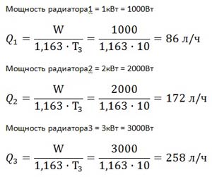
then, according to the formula

1.163 - heat capacity of water, W/(liter °C)
W - power, W.
where T 3 =T 1 -T 2 is the temperature difference between the supply and return pipelines.
The temperature difference is set from 5 to 20 degrees. The smaller the difference, the greater the flow rate and, accordingly, the diameter increases. If the temperature difference is greater, the flow rate decreases and the pipe diameter may be smaller. That is, if you set the temperature difference to 20 degrees, the flow rate will be less.
Find the diameter of the pipeline.
For clarity, it is necessary to bring the diagram into block form

Since the resistance in the tees is very small, it should not be taken into account when calculating the resistance in the system. Since the resistance of the length of the pipe will be many times greater than the resistance in the tees. Well, if you are a pedant and want to calculate the resistance in the tee, then I recommend that in cases where the flow rate is greater for a 90-degree turn, then use an angle. If it is less, then you can close your eyes to it. If the coolant moves in a straight line, then the resistance is very small.
| Resistance1 = branch 1 from tee2 to tee7 Resistance2 = radiator branch2 from tee3 to tee8 Resistance3 = radiator branch3 from tee3 to tee8 Resistance4 = branch 4 from tee4 to tee9 Resistance5 = radiator branch5 from tee5 to tee10 Resistance6 = radiator branch6 from tee5 to tee10 Resistance7 = path from tee1 to tee2 Resistance8 = pipe path from tee6 to tee7 Resistance9 = pipe path from tee1 to tee4 Resistance10 = path from tee6 to tee9 Resistance11 = pipe path from tee2 to tee3 Resistance12= pipe path from tee8 to tee7 Resistance13 = path from tee4 to tee5 Resistance14= pipe path from tee10 to tee9 Resistance of the main branch = from tee1 to tee6 along the boiler line |
For each resistance it is necessary to select a diameter. Each resistance section has its own flow rate. For each resistance it is necessary to set the declared flow rate depending on the heat losses.
We find the costs at each resistance.
To find the flow rate in resistance1, you need to find the flow rate in radiator1.
Calculation of diameter selection is carried out cyclically:
Further calculations for this problem are included in another article:
Answer: The optimal minimum flow rate is: 20 l/m. At a flow rate of 20 l/m, the resistance of the heating system is: 1m.
Of course, it is still necessary to take into account the resistance of the boiler, which can be taken to be approximately 0.5 m. Depending on the passage diameters of the boiler itself. In general, to be more precise, it is necessary to calculate in the boiler itself through the tubes. How to do this is described here:
How to wire a water heating system for a very large house
There is a universal scheme for water heating systems, which allows you to make the system more advanced, functional and very productive.
Above I already explained why such elements are needed:
Hydroarrow- this is actually a hydraulic separator, detailed explanation and the calculation of hydraulic arrows is explained here:
But I will repeat myself a little and explain some more details. Let's consider a circuit with a hydraulic separator and a manifold together.

V1 and V2 should not exceed a speed of 1 m/s; as the speed increases, unjustified resistance occurs at the inlet and outlet of the pipes.
V3 should not exceed a speed of 0.5 m/s; as the speed increases, resistance from one circuit to another is influenced.
F - The distance between the pipes is not regulated and is taken as minimal as possible in order to comfortably connect various elements(100-500mm)
R- The vertical distance is also not regulated and is accepted as a minimum of 100mm. Maximum up to 3 meters. But the distance (R) of the diameters of the four pipes (D2) would be more correct.
The main purpose of the hydraulic arrow is to obtain an independent flow rate that will not affect the boiler flow rate.
The main purpose of a collector is to divide one stream into many streams so that the streams do not affect each other. That is, so that a change in one of the collector flows does not affect other flows. That is, a very slow movement of coolant occurs in the collector. Slow speed in the reservoir has less effect on the flows leaving it.
We disassemble the inlet diameter from the boiler D1
One of the calculations of diameter is the following formula:

It is necessary to strive for the minimum speed of coolant movement. The faster the coolant moves, the higher the resistance to movement. The greater the resistance, the slower the coolant moves and the weaker the system heats.
Task.
Let's try to increase the diameter to 32mm.
Then the schedule will be like this.

Maximum flow rate 29 l/m. The difference from the original is 4l/m.
It's up to you to decide whether the game is worth the trouble... Further increase will lead to a pointless waste of money on large diameters.
Next, I take into account that each boiler will have a flow rate of 29 l/m. the flow rate from two boilers will be 58 l/m. Now I want to calculate what diameter to choose for the pipe that connects two boilers and goes into the hydraulic valve.
Finding the diameter after the tee
Given:
At a flow rate of 58 l/m, the resistance was: 0.85 m, basically the resistance creates about 0.7 m. To reduce the resistance of the mud filter, it is enough to increase its diameter or the thread on it. The greater the permeability of the mud filter, the less resistance it contains.
Therefore, we make a decision: Do not increase the diameter, but increase the mud filter, with a thread of up to 1.5 inches.
With this effect, we will significantly increase the total heat flow from the boiler to the water gun.
Also, by this effect of increasing the flow through the boiler, we increase the efficiency of the boilers.
Also, if we want to reduce the resistance of the check valve, then the thread on it should be increased. Therefore, we accept a 1.25-inch thread.
Ball valves should be selected in such a way that the internal passage does not narrow or increase, but exactly repeats the passage itself. Choose a passage in the direction of increasing diameter.
More information about hydraulic shooters:
According to the problem:

Heated floor consumption: 3439 l/h at a temperature difference of 10 degrees.
400m2 x 100W/m2 = 40000W
Regarding radiator heating, operating principle various schemes. I have not yet prepared articles on this topic, since most people know how to do it, at least approximately. But there are plans to touch upon this topic and prescribe strict laws and calculations for the development of circuits in space.
Regarding warm water floors
The diagram shows that warm water floors are connected through. The circuit forms through a three-way valve.
Mixing unit- this is a special pipeline chain that forms the mixing of two different flows. IN in this case For this purpose, two flows are mixed: the heated coolant from the collector and the cooled coolant returned from the heated floors. Such a mixture, firstly, gives reduced temperature, and secondly, it adds consumption to heated floors. Additional expense accelerates the flow of coolant through the pipes.
Engineering calculation of diameters for the required flow
For these calculations I have developed a section:
How to get rid of air in the heating system constantly?
The most the perfect way The following element is used to automatically remove air: Automatic air vent. But to use it effectively, it must be installed on the highest supply pipe of heating systems. In addition, you need to create an area of space in which the air will be separated.
See diagram:

That is, the coolant leaving the boiler must first rush upward to the air separation system. The air separation system consists of a tank with a thickness greater than the diameter of the pipe entering it by 6-10 times. The air separator tank itself should be at its highest point. There should be a .
The inlet pipe should be at the top, and the outlet pipe should be at the bottom.
When the coolant has low pressure, gases begin to be released in it. Also the most hot coolant has a more intense gas release.
That is, by pushing the coolant to the very top, we reduce its pressure and thereby the air begins to be released more intensely. Since the coolant immediately going into the air separator tank has the highest temperature and, accordingly, gas release will be intense.
Therefore, for ideal air release in a heating system, two conditions must be met: high temperature and low pressure. And low pressure is in the most high point.
For example, you can try installing a pump after the air separator tank, thereby reducing the pressure in the tank.
And why is this method of air release not used everywhere?
This method of releasing air has long been known!!! In addition, it greatly reduces the hassle of releasing air.
How to connect a solid fuel boiler
As is known solid fuel boilers are at risk of overheating due to failure of air shut-off mechanisms. For safe use Solid fuel boilers for high temperature heating systems use two main elements.
How a capacitive hydraulic separator works is described here:
Why are they dangerous? high temperatures for heating systems?
If you have plastic pipes such as polypropylene, metal-plastic, etc., then direct connections of such pipes to a solid fuel boiler are contraindicated.
The solid fuel boiler is connected only with steel and copper pipes, which can withstand temperatures over 100 degrees.
Pipes that can withstand high temperatures are assembled with temperature restrictions.
Three-way valves are mainly used with large bores and servo actuators. With mechanical movement, valves have a very narrowed flow area, so check the flow charts for these three-way valves.
The three-way valve in the boiler circuit serves to prevent low temperature With . Such a three-pass valve must allow the coolant to flow into the boiler at least 50 degrees.
That is, if the heating system is below 30 degrees, it begins to open the boiler circuit inside the boiler itself. That is, the coolant leaving the boiler immediately enters the boiler on the return line. If the boiler temperature is above 50 degrees, cold coolant begins to flow from (from the tank). This is necessary in order not to cause a strong temperature overload in the boiler circuit, since a large temperature difference causes condensation on the walls of the heat exchanger, and also reduces the favorable annealing of firewood. In this mode, the boiler will last longer. Also, ignition of the boiler will be faster and more efficient than if the boiler were constantly supplied with ice coolant.
The temperature of the solid fuel boiler must be at least 50 degrees. Otherwise, you need to reduce the temperature of the three-way valve not 50, but below degrees to 30.
At low temperature heating at 50 degrees, you need to take into account the decrease in temperature of the three-way valves. If you set the boiler to 50 degrees, then set the three-way valve of the boiler circuit to 20-30 degrees, and at the outlet 50 degrees. Also keep in mind that the higher the temperature pressure in the boiler, the higher the efficiency of the boiler. That is, a cooler coolant should flow into the boiler. Also, the greater the flow through the boiler, the higher the efficiency of the boiler. This is evidenced by heating engineering.
The flow rate through the boiler should be as high as possible for effective heat exchange (higher efficiency).
A three-way valve at the outlet to the heat consumer is needed in order to stabilize the temperature of the consumer and prevent high temperatures from entering.
For example, from a real object:


This article is finished, write comments.
This material belongs to the section: Water heating designer
| If you would like to receive notifications about new useful articles from the section: Plumbing, water supply, heating, then leave your Name and Email. |
Connecting solid fuel into one system solves the fuel issue for the owner. A single-fuel boiler is inconvenient because if you do not replenish supplies in a timely manner, you may be left without. Combination boilers are expensive, and if such a unit breaks down seriously, all the heating options provided in it will become unfeasible.
Using a heat accumulator
The diagram for connecting a gas and solid fuel boiler into one system looks like this: the gas boiler, heat accumulator and heating devices are combined into a common closed circuit, and the solid fuel unit transfers all the energy to the heat accumulator, from which the coolant already enters the closed system.
Such a network can operate in several modes:
- from two boilers simultaneously;
- only from gas;
- only from solid fuel through a heat accumulator;
- from solid fuel, bypassing the heat accumulator, with the gas boiler turned off.
How to connect two boilers to one heating system using this diagram. Shut-off valves are installed on the nozzles of the wood-burning boiler. An open expansion tank is installed at the highest point of this circuit and connected to the boiler supply pipe. Next, taps are cut into the supply/return pipes of the heat accumulator and connected with pipes to the rest of the circuit.
In order for the boiler to be used without a heat accumulator, in the vicinity of shut-off valves the latter, two tubes are cut in and shut-off valves are installed on them. Serving and return pipes connected by a bypass: it is attached to the supply jumper with a fitting or welding, to the return jumper - through three way valve.
Between the three-pass valve and the boiler, a circulation pump with a filter is built into the circuit. It is also recommended to make a bypass in this area around the pump: if the electricity is turned off, the coolant will be able to move due to natural circulation.
Installation of the “gas” circuit is carried out as in the usual scheme with heat accumulator. Expansion tank with safety valve, as a rule, is already included in the boiler design. A pipe leading to the heating appliances is connected to the supply pipe through a shut-off valve. The return line is also connected to the boiler through a shut-off valve. The pump is installed on the return pipe.

Jumpers are connected from both pipes to the heat accumulator: one - in front of the circulation pump, the second - in front of the heating devices. In these same places, connect the tubes that were installed in the primary circuit (for the movement of coolant from the boiler TD without a heat accumulator). All new connections are equipped with valves to shut off the flow.
Parallel closed circuit
How to connect a solid fuel boiler in parallel with a gas one?
In this case, a closed membrane tank and safety devices are used:
- air vent valve;
- safety valve (to normalize pressure);
- pressure gauge
Installation begins with the installation of shut-off valves on the supply/return pipes of both units. A safety group is installed at the supply of the TD boiler at a short distance from it.
When connecting a solid fuel boiler and a gas boiler in one system, on a branch from the TD unit, 1-2 meters from it, install a jumper to create a small circulation circle. The jumper is equipped with a check valve to prevent water from entering the “wood” part of the circuit if the solid fuel boiler is turned off.

The supply and return lines are carried out to the radiators. The return line branches into two pipes: one goes to the gas boiler, the second is connected to the jumper through a three-way valve. A closed membrane tank and a pump with a filter are installed in front of this branch.

The parallel scheme also does not exclude the use of a heat accumulator: supply and return pipes from both units are connected to it, and a direct and return line to the heating devices leaves from it. All components of the system are equipped with taps to shut off the flow, so that the boilers can be used both together and separately.
This is the answer to the question of how to connect solid fuel and gas boilers into one system if not only heating is required, but also hot water supply: purchasing a double-circuit boiler when you already have one is irrational (). It is better to use a second single-circuit () and a buffer capacity.
Video about how to connect solid fuel and gas boilers to one heating system.
The creation of a heating circuit, in which two boilers in the heating system operate either individually or together, is associated with the desire to provide redundancy or reduce heating costs. The joint operation of boilers in an integrated system has a number of connection features that should be taken into account.
 Possible options - two boilers in one heating system:
- gas and electricity;
- solid fuel and electricity;
- solid fuel and gas.
 Combining a gas boiler with an electric boiler in one circuit, resulting in a heating system with two boilers, can be implemented quite simply. Both serial and parallel connection are possible. Wherein parallel connection preferable because you can leave one boiler running while the other is completely stopped, turned off or replaced. Such a system can be completely closed, and ethylene glycol can be used as a coolant for heating systems or.
Combined operation of a gas and solid fuel boiler
 This is the most difficult option for technical implementation. In a solid fuel boiler it is extremely difficult to control the heating of the coolant. Typically, such boilers operate in open systems, And overpressure in the circuit when overheating is compensated in the expansion tank. Therefore, directly connect the solid fuel boiler to closed circuit it is forbidden.
For the joint operation of a gas and solid fuel boiler, a multi-circuit heating system has been developed, which consists of two independent circuits.
 The gas boiler circuit operates on heating batteries and on a common heat exchanger with a solid fuel boiler and an open expansion tank. For the room in which both boilers are installed, it is necessary to meet the requirements for both gas and solid fuel boilers
Combined operation of solid fuel and electric boilers
 For such a heating system, the operating principle depends on the type. If it is intended for open heating systems, then it can easily be connected to an existing open circuit. If the electric boiler is intended only for closed systems, then the best option will be – joint work on a common heat exchanger.
Dual fuel heating boilers
 To increase the reliability of heating and to avoid interruptions in the operation of the heating system, dual-fuel heating boilers are used, operating on different types of fuel. Manufactured combi boilers only in floor-standing version due to sufficient heavy weight unit. A universal unit may have one or two combustion chambers and one heat exchanger (boiler).
The most popular scheme is the use of gas and firewood to heat the coolant. It should be taken into account that solid fuel boilers can only operate in open heating systems. To realize the benefits closed system An additional circuit for the heating system is sometimes installed in the tank of a universal boiler.
 There are several types of dual-fuel combi boilers:
- gas + liquid fuel;
- gas + solid fuel;
- solid fuel + electricity.
Solid fuel boiler and electricity
 One of the popular combination boilers is a solid fuel boiler with an installed electric heater. This unit allows you to stabilize the temperature in the room. Thanks to the use of heating elements, such a combination boiler has acquired a lot of positive qualities. Let's look at how the heating system works in this combination.
 When igniting fuel in the boiler and connecting the boiler to electrical network The heating elements immediately begin to work, heating the water. As soon as the solid fuel ignites, the coolant quickly heats up and reaches the operating temperature of the thermostat, which turns off the electric heaters.
The combination boiler runs only on solid fuel. After the fuel burns out, the water begins to cool in the heating circuit. As soon as its temperature reaches the thermostat threshold, it will turn on the heating elements again to heat the water. This cyclic process will help maintain a uniform temperature in the rooms.
 To optimize heating circuits, heat accumulators in heating systems were invented, which represent a large volume capacity from 1.5 to 2.0 m3. During operation of the boiler, a large volume of water is heated from the circuit pipes passing through the storage tank, and after the boiler stops operating, the heated water slowly releases thermal energy into the heating system.
Heat accumulators allow you to maintain comfortable temperature for quite a long time.
To winter time To avoid critical situations, reduce heating costs and ensure its reliability, many owners prefer to either install a system with two boilers using different fuels, or install. These heating options have certain advantages and disadvantages, but they fully provide their main task - stable and comfortable heating.


