Before you start major renovation or construction of premises, it is important to think about placement locations in advance lighting fixtures, sockets and switches. If there are no problems with this issue, then you need to figure out how to connect all the wires and devices according to the diagram so that everything works correctly.
But before starting work related to electricity, you need to worry about safety precautions. Before installation, you need to turn off the power to the room being repaired, to do this, move the machine in the distribution panel to the lower position. This is necessary so that no one gets electrocuted.
Features of installation work
Installation and connection electrical devices such as sockets, switches or light sources is carried out only if the room being repaired is completely de-energized. Wherein there are some nuances carrying out such work.
- Electrical wiring according to the diagram should only be laid in straight lines, both vertically and horizontally.
- If the room is made of wood, then the wires are laid on the walls. In this case, there should be no direct contact between the electrical wiring and the surface of the walls. Installation takes place on special insulators that do not conduct current.
- In buildings made of stone or concrete, electrical wires are hidden in grooves under a layer of plaster.
If we consider electrical wires, they consist of a current-carrying core covered with insulation. There may be several such conductors in an electrical wire. In most cases, two and three-wire wiring is used. In this case, one core always creates a continuous circuit on which there is no voltage. This wire is neutral. The remaining cores are phase or working.
What might you need to connect?
To quickly and easily connect the switch from the socket to the light bulb, according to the diagram, you may need certain tools and supplies.
- Electrical circuit breaking device.
- Electrical wires corresponding to the electrical wiring installed throughout the building are copper or aluminum.
- A distribution box in which the wires are connected. Thanks to the boxes, all connections can be made efficiently, which reduces the risk of short circuits during the operation of electrical appliances.
- Screwdriver indicator with LED. Such a device is useful for determining the phase of the electrical network.
- Side cutters for cutting wires into pieces and connecting wires using twists.
- Insulating tape for insulating twists.
- Fastening elements for laying wiring in wooden buildings. Special clamps will allow you to securely secure the corrugation to a wooden wall. But the simplest and cheapest fastening is considered to be a metal strip from a tin can with a nail for fixation.
- Socket boxes designed for high-quality installation sockets or switches. Structurally, this product resembles a glass made of polymer material, non-conducting electricity.
And finally you will need a hammer drill. It is necessary for opening the plaster or, more simply, gating the walls. If the switch is installed in a new location, you will need a cutter to drill a hole for the socket box. Thanks to this core drill, creating a socket for installing a socket or switch will not be difficult.
Selecting a switch for connecting a light bulb
 Structurally, any switch consists of a housing in which the current-receiving part of the device and an electrical circuit breaker are located. The most common is considered rocker switch. At the same time, for convenience, several keys are often installed in one housing. Today, all switches can be divided into the following types:
- key switch design;
- pass-through switch;
- touch device;
- pulse circuit breakers.
I would like to note that it doesn’t make much sense to figure out how to connect each device separately, since they all have general scheme, used during installation single-key switch to the light bulb from the socket. Therefore, the design of such a device will be considered in more detail.
Block of such devices It is equipped with several contacts for connecting wires and a key for breaking the electrical circuit. However, most devices are equipped with a special fastening element. Usually these are two metal plates, the expansion of which is adjusted using ordinary screws.
Connection diagram for switch from socket
Almost all switches can be connected according to a generalized circuit to a light source - an electric light bulb. Moreover, regardless of the design of the electrical circuit breaker, its connection always occurs in the open phase, which is taken from the outlet. That is the switch breaks the working conductor of the electrical wiring.
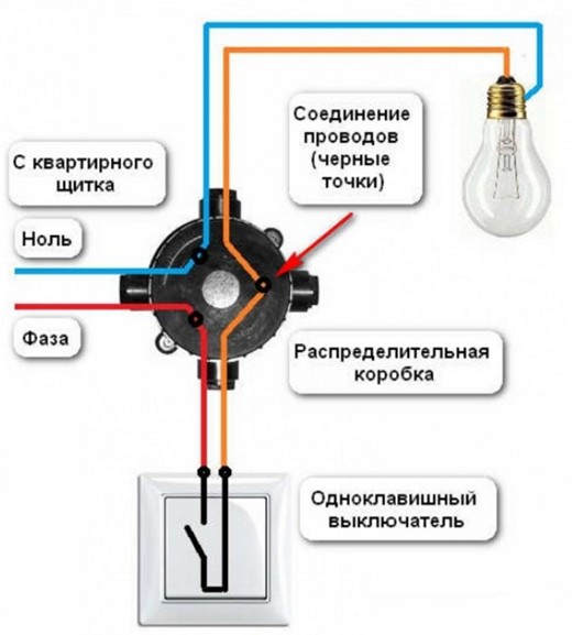
- The distribution box contains wires from a socket powered from the general electrical network, wires laid from the switch and wiring from the socket light bulb, where they will be connected to the AC network.
- One wire coming from the cartridge must be connected to the zero core, and the free end with wiring laid to the switch.
- The second wire is connected to the socket phase. Thanks to this, the light bulb together with the socket is connected to the phase through an electrical breaker.
When the switch is in the on position according to the diagram, the load will be supplied to the light bulb socket, and when the device is turned off, the supply of electricity is interrupted.
Marking locations for installation of electrical devices
 Before you start connecting, you must perform markup the location of the switch, which is best installed closer to the outlet and electrical wiring on the walls and ceiling where the lighting fixture will be mounted. Most often, the switch is fixed near front door into the room. If this is a walk-through room, then the switch is installed directly next to the doorway.
After marking the location for installing the switch a straight line is drawn up to the ceiling. A distribution box must be installed at this location. On ceiling surface the center of the room is determined. The light bulb will be connected at the marked location. A straight line is drawn from the cartridge to the wall. After this, the length of the drawn lines is measured, taking into account the distance from the outlet, and the wires are cut into pieces with a margin.
How to connect a switch from an outlet
 Installation work begins with the direct installation of an electrical circuit breaker in the vicinity of the outlet. If he mounted on wooden wall
, then an insulating plate made of plastic or other non-conductive material is installed; if the building is made of stone, then the switch is mounted in a socket box. But since most buildings are brick or concrete, all work is carried out in accordance with a specific plan.
Installation work begins with the direct installation of an electrical circuit breaker in the vicinity of the outlet. If he mounted on wooden wall
, then an insulating plate made of plastic or other non-conductive material is installed; if the building is made of stone, then the switch is mounted in a socket box. But since most buildings are brick or concrete, all work is carried out in accordance with a specific plan.
- The distribution box is installed. Next, you can connect the wire to the switch, which is hidden in the grooves.
- A special block with two current-receiving contacts is installed on the ceiling surface. In the future, a cartridge with wires will be connected to the block.
- The wire running along the ceiling is laid in grooves to the wall where the switch is located and goes into the junction box.
- Another piece of wiring goes from the box directly to the switch.
- A socket along with an electric light bulb is connected to the block on the ceiling. In most cases, these pads have a screw connector. The ends of the bare wires are inserted into the terminal blocks and secured with a screw.
- Next, all ends of the wiring in the junction box are twisted according to the diagram. To make the twist reliable, it is clamped with pliers.
- The wiring connections are insulated with special electrical tape.
- The electricity supply is turned off and the ends coming from the outlet are revealed.
- The power supply is restored and the phase wire in the socket is detected. To do this, the indicator touches the wires one by one and when it hits a phase, the LED on the screwdriver lights up.
- The socket phase is marked in any convenient way, and the room is de-energized again.
- All wires, both those coming from the switch and light bulb, and those laid from the socket, are put into the wiring distribution box.
- One core from the light bulb socket must be connected to neutral wire, and the second is connected to either end of the wiring coming from the switch. The free core from the switch is connected with the phase coming from the socket.
All twists are carefully crimped with pliers and are insulated with insulating tape. Electricity is supplied and the connection is checked. If the light source lights up, then all the boxes are closed and the grooves are sealed. Otherwise, you need to look for bad contact in the twists.
Installing sockets and switches is usually the final stage of renovation, which both new residents of the apartment and people who decide to update their home and make repairs have to go through. You can install the switch yourself, even without the help of a specialist.
How to choose a switch
Light switches come in the following types:
- single-key
- two-key
- sensory
- pulse
A single-key switch is best for connecting a switch.
How to properly connect a light switch - diagram. Connection diagram of a switch to a light bulb
Connecting a switch with one key is not difficult if you follow its connection diagram.
The switch connection diagram is quite simple and looks like this:
How to connect a light switch yourself
As a rule, two wires go from the general electrical panel in the apartment to the distribution box located at a height - zero and phase. A wire similar to the second one is drawn from the switch into the box and connected to it. Connecting wires also pass from the light bulbs and from the switch, which must be fastened together. The “zero” wire is also connected to the same one that comes out of the lamp. Thus, all the wires from the switch to the light bulbs pass through the box, and it itself serves as a switch, disconnecting the electric current from the light bulb switch by breaking the phase wire through which voltage is supplied. If you connect the wires incorrectly, you can switch the zero. In this case, when replacing the light bulb, the socket will still be energized, which can result in injury. You can check the wires and determine which of them is supplying voltage using an indicator. After identifying the wires and making the connection, you must correctly connect the switch to the socket box. It should be remembered that in older houses it may be difficult to install modern devices in Soviet-style socket boxes. Problems arise due to the fact that old and new socket boxes have different diagonals - for modern ones it is 67 mm, while the old ones were designed for the installation of more massive devices and have a diagonal of 70 mm. In this case, you may need additional installation for secure fixation of switches and sockets.
How to connect a switch. How to connect a switch to a light bulb
To connect the light bulb to the switch you will need:
- switch
- electrical wire
- distribution boxes
- electric indicator screwdriver
- wire cutters and pliers
- insulating tape
- fastener
- socket box
- hammer drill
The diagram for connecting the switch to the light bulb is as follows: in distribution box All wires in the apartment must be connected, as well as the wires coming from the switch and lamp. The working conductor of the network is connected to the working conductor of the light bulb through a switch so that one wire of the socket is connected to the neutral conductor of the network, and the second to the conductor of the wire that comes from the switch.
The diagram for connecting a light bulb to a switch is quite simple. By following this diagram, the switch will be connected correctly.
Correct connection of the switch. At what height should the light switch be placed?
Before connecting the switch, you need to establish the level at which it will be located.
Sockets and switches can be installed at any height. During the Soviet period, sockets were located at table level, and switches were located quite high. Now the sockets are placed low. This is due to the large number of constantly connected devices and the reluctance to pass bundles of wires in plain sight. Switches also began to be mounted much lower, at a distance of about 1m from the floor. Typically, this is to ensure that turning lights on and off in rooms is easy for short people. You can install the switch in the most convenient place for you.
Self-installation of the switch
First you need to install the switch. If the switch is mounted on wooden surface, you need to install a die made of plastic or wood. After this, install the junction box and then connect the switch and the wire, insert it into the corrugation, and attach it to the wall.
Install a block with two current-receiving contacts on the ceiling. Insert a piece of wire for the lamp into the corrugation and bring it to the wall with the switch. Put it in a separate box. After this, take another piece of wire, enclose it in a corrugation and lead it into the main box.
Connect the wire with the lamp and socket to the block on the ceiling, wrap the ends of the wires around the bolt. Twist the ends of the wires in the first distribution screwdriver.
Isolate twists. Turn off the electricity, open the ends shared network and turn the electricity back on. Using a screwdriver, find the zero phase and mark it.
Bring the ends of all the wires into the box, connect them - connect the end of one wire to zero phase network, the other with the switch wire.
Connect the free wire of the switch to the working residential network. Twist the ends with pliers, insulate them with tape, and put the siza on top.
Turn on the switch and check its operation.
How to safely connect a switch. Safety precautions for connecting a light switch to a light bulb
If you need to connect a light switch with one or more keys, very often non-professionals make the same mistake - they connect zero to the switch, not phase. Thus, a wire supplying voltage passes through the chandelier, and when the light is turned off, the circuit is interrupted, but a zero break occurs, while the cartridge in the lamp remains energized. When changing a lamp, a person acts as a ground and current passes through him. Therefore, all work on repairing or replacing electrical wiring is carried out by de-energizing the room and following the connection diagrams.
Gone are the days when the wiring diagram for electrical appliances, including lamps, was “customized” to fit existing switching devices, taking care of optimal location the latter. Currently, different in functionality and technical capabilities There is such a variety of switches, switches, and so on that you can safely do the electrical wiring in such a way that turning on and off the electrical appliances used is as convenient as possible for their user. A special case is lighting control from two places (points), that is, a pair of switches.
Options and advantages of using lighting control with two switches
The classic diagram for connecting one lamp (lamp) is known to everyone. You need 1 switch, which is located in the most accessible or convenient place for lighting control: at the beginning or middle of passage rooms, long corridors, galleries, alleys (); at the entrance to the premises or entrance, and so on. Almost everyone has experienced how inconvenient this can be.
And now the same and other options for controlling lighting devices, but using 2 switches:
- In walk-through rooms and premises, as well as buildings with two entrances (garages, sheds, outbuildings for keeping pets or poultry), especially when they are opposite. Installing one switch for each input will eliminate the unpleasant need to walk in the dark to turn on the light or after turning it off. After all, it often happens that you need to enter through one door and exit through another.
- In corridors, galleries, alleys (paths in the garden), etc., especially when they are long, connecting two switches - one at each end of these objects - will ensure not only convenient use of light, but also its saving. After all, it will be possible to use the lighting when moving in any direction and immediately turn it off after passing this section of the path.
- In the entrance of a residential apartment building or on the stairs between floors of a private two-story house. There are also 2 switches here, both convenient and economical.
- In the bedroom. If you place one switch at the entrance and the other at the head of the bed, you won’t have to get up to turn off the light when it’s time to fall asleep. And vice versa, when you wake up, you can immediately, without getting up, turn on the lighting, and then turn it off only when leaving the bedroom, without returning to the bed. This is especially convenient when the bedroom is large.
- And in many other cases, when there is a need to control one lighting fixture from two places.

As you can see from the examples, 2 switches are not only very convenient, but also save energy, that is, ultimately, money. After all, the light can be turned off as soon as it is no longer needed. And it does not need to be left all night, as was the case with the 1st switch, for example, in long corridors, when returning to their beginning to de-energize the lamps did not make sense. After all, the light was turned on to go through this corridor.
What switches are needed to control the light from two points - name and design
The considered use of two switches assumes that, regardless of the position of the switching contacts of one of them, the other can always turn the lighting on or off at any time. Conventional switches, which humanity has used since the invention of electricity, are completely unsuitable for this. After all, they are not initially structurally designed for such work, because in one of their two positions they open (break) the electrical circuit. Therefore, no matter how you connect them, it doesn’t matter if one of them has open contacts, the other will never turn on the electrical appliance. And they must be connected somehow to each other, since it is assumed that they will be used to control the operation of the same lamp, that is, installed as part of one common electrical circuit.
To independently control lighting and other electrical appliances from two places, so-called pass-through switches, which have recently appeared on the market of electrical goods, are used.
They are also called pass-through switches or changeover switches and switches. There are also cross switches, but these are slightly different and more complex devices, used in conjunction with walk-throughs to control electrical appliances from three or more points. They can be installed instead of walk-throughs, but they will cost more, but vice versa cannot be changed. Externally with front side These switches are no different from ordinary switches. The same body and 1 or 2 keys (sometimes a different type of control part) for turning on and off.
Externally, the pass-through switch differs from regular switch in the following: with reverse side housing, where they are connected, it has 3 terminals for them. That is to pass-through switch 3 conductors are connected. A regular switch has only 2 terminals (a cross switch has 4). This is if the switching device is single-key.
If you need to control 2 groups of lamps of one lamp, that is, you will need two-key (double) pass-through switches, then you need to look for devices with six terminals for the connected wiring. Dual conventional switches have only 3 terminals (crossover switches have 8).

And now about the internal design differences and the resulting differences in work. The circuit supplied to the pass-through switch leaves it along 2 lines, between which it switches. That is, in each of its 2 positions, this switch closes one line coming out of it and breaks the second. It turns out that he never breaks the chain passing through him. How does it work in practice and provide independent management using 2-pass switches with 1 electrical appliance, is discussed in the next chapter and is clearly visible in the diagrams given in it.
Connection diagrams and operating principle of two pass-through switches in one circuit
There is only one way to connect two pass-through switches to switch one lighting or some other electrical appliance or several connected in series, that is, combined into one group. So it's impossible to go wrong with this. Below is a wiring diagram for one lamp.

In this standard scheme It can be seen that the pass-through switches are connected in series one after another in an open circuit between the electricity consumer and the phase. Moreover, they must be connected by 2 wires. In the following diagram of two switches for one light bulb, you can more clearly examine the operation of the entire circuit as a whole.

In the previous figure, the electrical appliance was turned on, and in this one it was turned off with switch No. 2. Obviously, the same action could have been done with switch No. 1. And from the current position of the switches it is clear that any of them can again power the electrical appliance.
It is very easy to assemble such a circuit. For switches, exactly as shown in the figures, the input (common) terminal for phase or zero is located on one side of the housing, and 2 output terminals are on the other. So, feel free to connect them, in any order, with 2 wires to each other. And then, to the already connected switches, we connect the rest of the wiring: to one of them, to which the zero is connected, and to the other - the phases. Since all electrical devices must be connected through a junction box, below is a diagram correct assembly the entire chain using it.

To turn 2 groups of electrical appliances on and off, you will need dual (with two keys) pass-through switches. Next diagram just for such a circuit, assembled using a junction box.

It is clearly visible in the figure and in the comments to it it is written that pass-through switches of 2 different modifications will be required - one with a phase connection from above, and the other from below. Despite its apparent complexity, this circuit is quite simple to make. On the switches, exactly as shown in the figure, there are arrow-shaped marks that tell you which wire goes where.
The development of an indoor electrical network can be planned both during its initial design and during the operation of ready-made wiring. In any case, the connection between distribution boxes, mounted socket boxes, switches - I want to do it with minimal costs on the material. Disconnection of the power cable is not necessarily carried out exclusively in installation boxes, which are hub splitters. For example, there are many ways to connect a switch to an outlet, and vice versa. Some of the switching can be done in any box, the main thing is that there is no danger of shorting the contacts.
A typical example of combining a socket and switch in one unit
Often in a corridor or hallway there is a need to combine a network connection point (socket) and a switch for several lighting groups. This method solves several problems:
- An extensive electrical outlet network in the corridor is usually not needed: there are no constantly used electrical appliances. However, there is a need to connect a vacuum cleaner or charger. In addition, a radiotelephone base unit can be installed in the hallway.
- There is little space on the walls in this room, installed wardrobe cabinets, mirror, hanger. Part of the corridor is usually occupied by the input switchboard and metering device (meter). Therefore, compact placement of switching equipment is a key issue.
- By combining the socket and switch, wiring is saved and installation of an additional junction box is not required.
- If you additionally connect a second device: a switch to a socket, or vice versa, there is no need to damage the wall or organize a route for the power cable. The connection is made with minimal impact on the room.
As can be seen in the illustration, to implement the entire scheme you will need one circuit breaker(on the dashboard it can be called “corridor: lighting, socket”), and one junction box.
The zero bus N (blue color) passes through a kind of transit to the lighting groups and to the socket. The PE grounding is inserted into the socket body, and (if one of the lighting groups is in the bathroom) into the lamp body. The phase after the machine is connected to the socket through the distribution box. The disconnection occurs in the socket box. In this case, any terminal block is used: for example, WAGO.

A small section of wire connects the phase terminal in the socket and the input terminal two-gang switch. Next, a phase is laid from the output terminals to each lighting group.
This scheme is usually used when designing, since you will still have to lay cables on different groups lighting. If such a solution is optional, you do not install additional boxes. The hole for the switch or socket box is made next to the already mounted device. All that remains is to install additional wiring.
If there is a need to connect the outlet and lighting to different machines protection (for example, a power socket is used for a powerful electrical appliance), the phase is initiated via different power lines.

There is no need to use an additional distribution box; the phase wire passes through it in transit, without disconnection.
Tip: Leave a loop on each phase wire in the distribution box. With the future expansion of the network, you can cut the wiring and quickly organize the connection using connectors.
In any case, this installation method saves both wiring and wall space. For example, let's look classic version connecting the socket and switch to the distribution box.

Two cable routes were laid, the connection was in the junction box. Looking at the diagram, it becomes obvious that connecting the switch directly to the outlet is more efficient.
How to connect a single-key switch from an outlet
The classic option: a common zero bus from the distribution box is connected to a light point.

Grounding goes through the same cable channel (if used). But the phase wire does not go directly to the lighting fixture. A single-key switch (located in the same housing as the socket) breaks the circuit between the phase contact in the socket box and the light source. Quite a common scheme. Such a block can often be found in lighting stores.

Another application of such a module is a switchable socket. Let's say you have an electrical appliance that should be turned off at night or when leaving the room. This could be a router that distributes Wi-Fi. The unit itself is located high, so it is not always possible to use the standard power button. By clicking the switch key, you will de-energize the equipment without touching the circuit breaker in the distribution panel. Or vice versa: the device must be powered at certain conditions. For example, power supply for an alarm system.
In this case, the phase wire inside the block is simply opened by a switch, and the power wiring is connected as to a regular socket.
If a switch is being added to an existing outlet
Minimizing the consequences - replacing the socket with a block. The procedure itself is simple; we drill a hole nearby for the box and carefully install the new module.

There is no need to install a power incoming cable; it is already in the socket. But the output wiring will have to be extended to the lighting device. This individual solution, there is no universal way. The connection diagram is very simple: both the neutral and phase wires are laid not from the box, but from the socket box.

Naturally, you will have to install contact blocks. Although many connect the output wire directly to the socket contacts: some models allow such a connection.
If there are several sockets in a group, replace them with common block(socket - switch) you can use any of them. You simply choose a convenient location (from which you can run the wire to the lamp) and connect the switch to the outlet.

If you need to organize an additional light point in the hallway, you can use wall sconces. They are placed in close proximity to the socket-switch unit, and you do not have to destroy big piece walls for wiring.

General safety rules
Of course, before starting such work (especially on a completed power supply system), you should de-energize the line and check that there is no voltage. Selecting a power cable will not cause any difficulties: a cross-section of 1.5 mm² is sufficient for organizing lighting. Since we are connecting the switch to the socket, and not vice versa, the primary (socket) cable will be more powerful: 2.5 mm².
Is it possible to connect an outlet to the switch?
Imagine the situation: you have renovated your premises, all the electrical wiring is walled up in the walls, and there are no backup boxes or socket boxes. An outlet needs to be installed in one of the rooms. Placing it next to the distribution box is irrational, the location is too high. And lay open wiring(especially, I don’t want to ditch the wall).
IN convenient location There is a switch that clearly has voltage. How to make a socket from a switch if it is possible to aesthetically place them next to each other?
To answer this question, let’s remember: what types of lighting schemes with switches are there?
Classic connection: tap from the distribution box.
The neutral conductor is inserted into the lamp from the box. In the box itself, a break in the phase cable is organized (it is opened using a switch), then the phase enters the lamp along the same path as the zero.
With this scheme, only the phase conductor is present in the body (installation box) of the switch. It will not be possible to organize a closed electrical circuit to connect an additional electrical appliance (via an outlet). You can use the phase from the switch, but you still have to lead the zero from the distribution box, which makes the idea pointless.
Conclusion: With this type of lighting arrangement, it is impossible to connect the socket to the switch.
The switch is located between the power source and the lighting fixture.
This scheme is less common, but in some rooms it is used. If at the design stage it was decided not to use distribution boxes in the lighting network, you are in luck. The switch wiring box contains both neutral and phase wires.

The sequence of work is as follows:
- We dismantle the existing switch without touching the installation box.
- We determine the routes for laying the input and output cables. If you have a diagram and plan for the electrical supply of the room, this is not difficult to do.
- Carefully drill a hole for the socket box.
- We install terminal blocks in the switch box and connect the socket according to the following diagram:

Safety regulations:
Since the current wiring is intended for lighting, most likely the cable cross-section is no more than 1.5 mm². The maximum possible load for such a cable (provided that it is copper): 3.3 kW. That is, not very powerful electrical appliances can be plugged into this outlet. The maximum is a vacuum cleaner. well and charging device for phones, router power supply or antenna amplifier - no problem.
Bottom line
Extension power network V separate room, due to disconnection in existing switching devices is possible. As a rule, the switch is connected to the outlet. The opposite situation is possible only with a certain wiring diagram.
Video on the topic
Connecting a single-key light switch is a task that sometimes faces a home electrician. Most lighting fixtures are controlled by these types of switches. This article discusses in detail the sequence of actions for connecting a single-key switch and installing it at home without outside help.
Preparatory work before installing the switch
To connect the light switch, preliminary preparations must be made. Installation is carried out from the nearest distribution box to which power is supplied - network cables supply of electric current.
Power to the switch and lamps is supplied from the distribution box
Three lines are laid - one from the junction box to the lamp, the other from it to the switch. The third one comes from the shield. As a rule, two- or three-core wires of the installation type are used, i.e., with a copper (or aluminum) conductor made of solid metal. In everyday life, such a wire is called hard, in contrast to soft, in which under the insulation there are pigtails of small hair conductors. On the label rigid cable denoted by the letter "U". The cross-sectional area of the conductor is selected in accordance with the load. For ordinary lamp or a chandelier in which up to 3 lamps are combined, a wire with a cross-sectional area of 1.5 mm 2 is sufficient.
If energy saving or led light bulbs, the cross-section of the conductor can be reduced to 0.75 mm 2 in order to save money.
The type of wiring installation can be of two types - internal (hidden) and external. Hidden wiring installed in the thickness of the wall or ceiling. The outer one runs along their surface, the cable is packaged in a corrugation or cable channel, which is attached to the wall with special brackets or other fastening material.
After the wires are separated, you can begin installing the switch.
Single-key switch connection diagram
The principle of operation of the switch is based on breaking the power supply circuit of a light bulb or any other device. Switching the toggle switch activates a contact pair, which disconnects the power wire from the current consumer.
The switch usually opens the phase wire
When assembling the circuit, you should pay attention to the reliability of the contacts. If the wires have large gaps, then at one point a so-called electric arc, the temperature of which is sufficient to melt and ignite the insulation. This can lead to smoke in the living space and even a fire. In order to avoid such phenomena, the following connection methods are used:

Twisting of copper and aluminum wires is also possible. But if the connection is overloaded, aluminum may melt, since it has more low temperature melting than copper. The contact will be interrupted.
Tools and materials for connection
To connect you will need the following tools:
- Electrical screwdriver.
- Household voltage indicator.
- Pliers.
The materials on hand should be:
- Wires of the required length.
- Terminal blocks or electrical tape.
- Lamp socket (and the lamp itself).
Pay attention to our article, which describes in detail how to choose the right switches:.
Photo gallery: materials for switch installation
The cable length is pre-measured with a tape measure at the work site  Depending on the type of wiring, you need to use external or built-in (internal) distribution boxes
  The cartridge is attached to the ceiling with self-tapping screws
  The base of the “correct” switch can be ceramic or high-quality plastic
Step-by-step instructions for connecting a single-key switch
If all the tools and materials are ready, you can begin assembly. The procedure can be divided into two steps:
- connecting switch contacts and light bulbs;
- switching cables inside the distribution box.
Before this, all wires are fixed in their designated places in cable ducts or corrugation. The distribution box and socket for the switch are firmly installed in (or on) the wall. The procedure has no of great importance, but experienced electricians always start connecting from the periphery - a switch and a light bulb, and end by connecting the wires in the box.
Connecting the switch and lamp

Exist various models switches, but for the most part they are secured in the socket box using a spacer mechanism mounted on the base. Before attaching the base, you need to connect the wires to it. To do this, the screws of the clamps are loosened, the wires are inserted into the sockets, and the screws are clamped again. It is important not to overtighten the threaded fastener - you need to tighten it so as not to damage the screw slots.
If there is no socket box and the switch is attached externally, screw the base to the wall surface with two screws.
The external switch is installed directly on the wall surface
At this stage it needs to be positioned correctly. It is customary to install the switch so that turning it off is done by pressing the button down, and turning it on is done up. This is done for security reasons. If something accidentally falls on the switch from above, the mechanism will break the circuit and turn it off.
After screwing the screws into the wall and securing the base, the installation of the switch can be considered complete. All that remains is to insert the key into place, but this can be done at the very end, after checking the operation of the entire circuit.
Connecting cables in a junction box
Before connecting conductors, it is necessary to de-energize the line supplying electric current to the junction box. To do this, you need to turn off the plugs or the automatic breaker on the meter panel.
It is very convenient to carry out switching according to the color of the cores. Using a voltage indicator, you need to determine which core contains the phase and which contains the zero. Touching the phase wire will cause the diode on the probe to glow.
The indicator is activated by placing your finger on the red cap
Typically, the “phase” is connected to the red wire of the wire, “zero” to the blue, and “ground” to the white.

If the wiring in the house is made with three-core cables, all the white ground conductors are connected to each other.
Video: connection diagram for a single-key switch
You may also find the connection instructions helpful. pass-through switch: .
How to connect 3 sockets and 1 switch from one junction box
Sometimes you need to connect one or more additional sockets to the existing wiring. This can easily be done by running another cable into the junction box.
It should be noted that for sockets it is customary to use connecting wires with larger area sections. This is due to the fact that a variety of Appliances. This could be a kettle or, for example, a vacuum cleaner. Their power consumption is higher than that of a simple light bulb, and therefore the thin wires can heat up, which is undesirable. Therefore, sockets are connected with cables whose cross-section starts from 2.5 mm 2.
The connection process consists of connecting the wire to the power line that comes to the distribution box from the switchboard. As with the installation of the switch, all work should be carried out only with the plugs turned off.

When connecting wires using twists, it is advisable to thoroughly clean all contacts with a knife or fine file. Sometimes old wiring oxidizes at the joints and the contact becomes unstable. When adding new wires, twisting is done using pliers.
To avoid short circuit insulation must completely eliminate possible contacts wires with different poles.
Video: connecting a single-key switch and socket
How to connect a one-key switch to two light bulbs
If you need to turn on two light bulbs at the same time from one switch, located in different places, the same connection diagram applies.
The supply of current to the lamps is controlled by one switch, but the connection options for the lamps themselves may vary.
New cable in box
Another cable is inserted into the junction box. The ends of the conductors are stripped and connected to the same terminals as the first lamp. This will take up some additional space inside the box, but if there is enough space, then nothing bad will happen.
One way to connect two light bulbs to one switch is to connect both pairs of wires to the same terminals
Cable from an existing device
A tap is mounted from an existing lamp, which is connected to it in parallel. To do this, two additional contacts (“zero” and “phase”, red and blue) are inserted into the socket of the first lamp and extended to the second lamp.
Advantage parallel circuit connection of lamps is the possibility of using them in any quantity
The choice of connection is selected depending on the situation. The second option is used more often, since there is often not enough space in the distribution box for input additional cables. In addition, in this way you can connect not only two lamps, but also a larger number of them. The main thing is to follow the principle parallel connection wires
Do you want the lamps to turn on smoothly? See connection diagrams for such a system in our next material: .
When installing household electrical equipment, you need to remember to comply with safety standards. Before starting work, be sure to turn off the power supply. It is better to use tools with dielectric coating and cables of the appropriate cross-section. Do not throw bare ends of conductors onto radiators or water pipes. In addition, the standard connection parameters must be observed.


